Микроконтроллеры AVR можно программировать через ICSP (ISP) интерфейс. Делать это не сложнее, чем пользоваться платой Arduino с загрузчиком (bootloader) в микроконтроллере. С технологией ICSP Вам также будет доступна среда программирования Arduino, а кроме того, и много других возможностей.
Возьмём AVR микроконтроллер ATtiny88 и попробуем программировать его используя технологию ICSP.
Для программирования микроконтроллера по технологии ICSP нужен программатор. Чаще всего, подойдёт самый дешёвый USBASP программатор. Казалось бы, программатор лишнее устройство, ведь для платы Arduino он не нужен. Но на плате Arduino уже припаяна микросхема, выполняющая ту же роль что и программатор USBASP для отдельно взятого микроконтроллера. И стоимость платы Arduino примерно равна стоимости микроконтроллера с программатором USBASP. Для знакомства с программированием микроконтроллеров проще приобрести плату Arduino, а работать с микроконтроллерами удобнее с программатором.
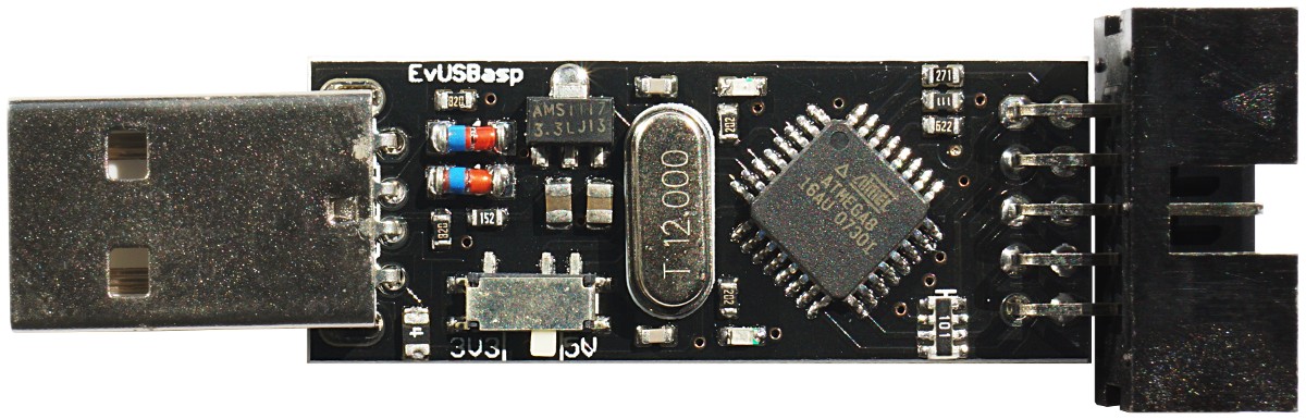
Рис. 1. Программатор USBASP.
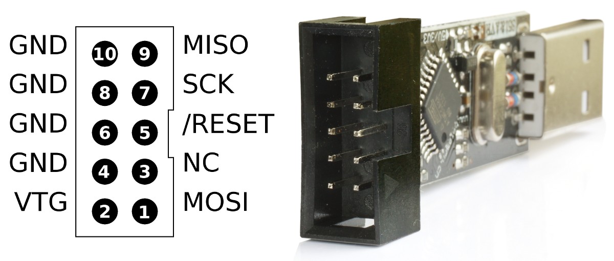
Рис. 2. Интерфейс программатора для внутрисхемного программирования микроконтроллеров.
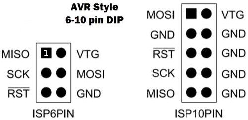
Рис. 3. Варианты интерфейсов для внутрисхемного программирования микроконтроллеров.
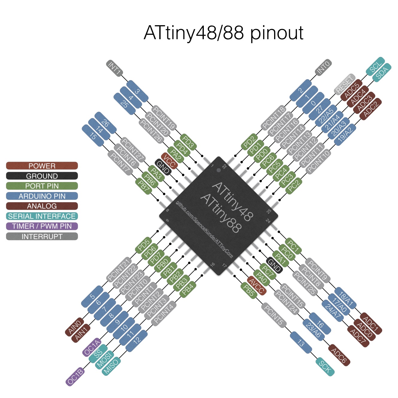
Рис. 4. Микроконтроллер AVR ATtiny88.
Для программирования микроконтроллера по технологии ICSP будем подключать к программатору следующие ножки микросхемы ATtiny88:
| Pin | Сигнал | Описание |
|---|---|---|
| 15 | MOSI | Вход данных при программировании |
| 16 | MISO | Выход данных при программировании |
| 17 | SCK | Вход тактового сигнала при программировании |
| 29 | RESET | Сброс |
| 5 | GND | Общий провод |
| 4 | VCC | Питание микросхемы |
Табл. 1.
Обратите внимание, что ножки микроконтроллера 15, 16, 17 задействованные в программировании микроконтроллера, после программирования могут быть задействованы как и все другие ножки микроконтроллера в ваших схемах. Если к этим ножкам уже припаяны периферийные устройства, они не помешают перепрошивке микроконтроллера в дальнейшем.
Подключаем микроконтроллер к программатору согласно рис. 2-3 и табл. 1. Подключаем программатор в USB порт компьютера и пытаемся с помощью программы avrdude считать сигнатуру микроконтроллера:
avrdude -cUSBASP -pt88
avrdude: warning at /home/dior/.avrduderc:56: part 8052 overwrites previous definition /home/dior/.avrduderc:5.

avrdude: warning: cannot set sck period. please check for usbasp firmware update.
avrdude: error: program enable: target doesn't answer. 1
avrdude: initialization failed, rc=-1
         Double check connections and try again, or use -F to override
         this check.


avrdude done.  Thank you.
Скр. 1. Программатор не смог связаться с микроконтроллером.
На скриншоте 1 программа avrdude рекомендует воспользоваться ключом -F.
avrdude -cUSBASP -pt88 -F
avrdude: warning at /home/dior/.avrduderc:56: part 8052 overwrites previous definition /home/dior/.avrduderc:5.

avrdude: warning: cannot set sck period. please check for usbasp firmware update.
avrdude: error: program enable: target doesn't answer. 1
avrdude: initialization failed, rc=-1
avrdude: AVR device initialized and ready to accept instructions
avrdude: Device signature = 0x108277
avrdude: Expected signature for ATtiny88 is 1E 93 11

avrdude done.  Thank you.
Скр. 2. Запуск avrdude с ключом -F.
На скриншоте 2 программа avrdude считала неверную сигнатуру микроконтроллера. Повторный запуск avrdude выводит другую сигнатуру. Мы получим тот же результат если отключим микроконтроллер от программатора.
Что же это такое происходит? Мы купили поддельный микроконтроллер? А может дело в Фьюзах? В микроконтроллере ATtiny88 имеется 3 восьми-битных регистра, отвечающих за предварительную настройку параметров работы микроконтроллера именно они называются фьюзами (FUSE). Фьюзы - это энергонезависимые ячейки памяти. Каждый бит в фьюзах меняет какие-то настройки микроконтроллера. Программируются фьюзы побайтно. Существуют удобные он-лайн калькуляторы фьюзов.
Пока наш программатор USBASP не видит микроконтроллер ATtiny88 мы не можем изменить даже фьюзы. Для прошивки фьюзов можно воспользоваться более дорогим программатором или собрать не дорогое, но относительно сложное устройство для изменения фьюзов. Нам показалось самым простым вариантом, воспользоваться программатором сделанным из платы Arduino, например, Arduino NANO или UNO. Следует отметить, что вариант с программатором из платы Arduino не универсальное решение, он не поможет если в микроконтроллере заблокирована функция RESET, но в новом микроконтроллере это маловероятно.
Чтобы превратить Arduino в программатор необходимо загрузить в него программу ArduinoISP. Эта программа есть в любой Arduino IDE в примерах. (меню Файл / Примеры).
Мы предполагаем, что заводские установки фьюзов в микроконтроллере ATtiny88 настроены на слишком низкую частоту работы тактового генератора микроконтроллера, поэтому, возможно, программатор USBASP не смог связаться с микроконтроллером. Значит и программатор ArduinoISP необходимо настраивать на самую низкую скорость работы.
Раскомментируйте в программе ArduinoISP строчку #define SPI_CLOCK (128000/6), а строчку #define SPI_CLOCK (1000000/6) наоборот закомментируйте.
// ArduinoISP
// Copyright (c) 2008-2011 Randall Bohn
// If you require a license, see
// http://www.opensource.org/licenses/bsd-license.php
//
// This sketch turns the Arduino into a AVRISP using the following Arduino pins:
//
// Pin 10 is used to reset the target microcontroller.
//
// By default, the hardware SPI pins MISO, MOSI and SCK are used to communicate
// with the target. On all Arduinos, these pins can be found
// on the ICSP/SPI header:
//
//               MISO °. . 5V (!) Avoid this pin on Due, Zero...
//               SCK   . . MOSI
//                     . . GND
//
// On some Arduinos (Uno,...), pins MOSI, MISO and SCK are the same pins as
// digital pin 11, 12 and 13, respectively. That is why many tutorials instruct
// you to hook up the target to these pins. If you find this wiring more
// practical, have a define USE_OLD_STYLE_WIRING. This will work even when not
// using an Uno. (On an Uno this is not needed).
//
// Alternatively you can use any other digital pin by configuring
// software ('BitBanged') SPI and having appropriate defines for PIN_MOSI,
// PIN_MISO and PIN_SCK.
//
// IMPORTANT: When using an Arduino that is not 5V tolerant (Due, Zero, ...) as
// the programmer, make sure to not expose any of the programmer's pins to 5V.
// A simple way to accomplish this is to power the complete system (programmer
// and target) at 3V3.
//
// Put an LED (with resistor) on the following pins:
// 9: Heartbeat   - shows the programmer is running
// 8: Error       - Lights up if something goes wrong (use red if that makes sense)
// 7: Programming - In communication with the slave
//

#include "Arduino.h"
#undef SERIAL


#define PROG_FLICKER true

// Configure SPI clock (in Hz).
// E.g. for an ATtiny @ 128 kHz: the datasheet states that both the high and low
// SPI clock pulse must be > 2 CPU cycles, so take 3 cycles i.e. divide target
// f_cpu by 6:
#define SPI_CLOCK (128000/6)
//
// A clock slow enough for an ATtiny85 @ 1 MHz, is a reasonable default:

// #define SPI_CLOCK 		(1000000/6)


// Select hardware or software SPI, depending on SPI clock.
// Currently only for AVR, for other architectures (Due, Zero,...), hardware SPI
// is probably too fast anyway.

#if defined(ARDUINO_ARCH_AVR)

#if SPI_CLOCK > (F_CPU / 128)
#define USE_HARDWARE_SPI
#endif

#endif

// Configure which pins to use:

// The standard pin configuration.
#ifndef ARDUINO_HOODLOADER2

#define RESET     10 // Use pin 10 to reset the target rather than SS
#define LED_HB    9
#define LED_ERR   8
#define LED_PMODE 7

// Uncomment following line to use the old Uno style wiring
// (using pin 11, 12 and 13 instead of the SPI header) on Leonardo, Due...

// #define USE_OLD_STYLE_WIRING

#ifdef USE_OLD_STYLE_WIRING

#define PIN_MOSI	11
#define PIN_MISO	12
#define PIN_SCK		13

#endif

// HOODLOADER2 means running sketches on the ATmega16U2 serial converter chips
// on Uno or Mega boards. We must use pins that are broken out:
#else

#define RESET     	4
#define LED_HB    	7
#define LED_ERR   	6
#define LED_PMODE 	5

#endif

// By default, use hardware SPI pins:
#ifndef PIN_MOSI
#define PIN_MOSI 	MOSI
#endif

#ifndef PIN_MISO
#define PIN_MISO 	MISO
#endif

#ifndef PIN_SCK
#define PIN_SCK 	SCK
#endif

// Force bitbanged SPI if not using the hardware SPI pins:
#if (PIN_MISO != MISO) ||  (PIN_MOSI != MOSI) || (PIN_SCK != SCK)
#undef USE_HARDWARE_SPI
#endif


// Configure the serial port to use.
//
// Prefer the USB virtual serial port (aka. native USB port), if the Arduino has one:
//   - it does not autoreset (except for the magic baud rate of 1200).
//   - it is more reliable because of USB handshaking.
//
// Leonardo and similar have an USB virtual serial port: 'Serial'.
// Due and Zero have an USB virtual serial port: 'SerialUSB'.
//
// On the Due and Zero, 'Serial' can be used too, provided you disable autoreset.
// To use 'Serial': #define SERIAL Serial

#ifdef SERIAL_PORT_USBVIRTUAL
#define SERIAL SERIAL_PORT_USBVIRTUAL
#else
#define SERIAL Serial
#endif


// Configure the baud rate:

#define BAUDRATE	19200
// #define BAUDRATE	115200
// #define BAUDRATE	1000000


#define HWVER 2
#define SWMAJ 1
#define SWMIN 18

// STK Definitions
#define STK_OK      0x10
#define STK_FAILED  0x11
#define STK_UNKNOWN 0x12
#define STK_INSYNC  0x14
#define STK_NOSYNC  0x15
#define CRC_EOP     0x20 //ok it is a space...

void pulse(int pin, int times);

#ifdef USE_HARDWARE_SPI
#include "SPI.h"
#else

#define SPI_MODE0 0x00

class SPISettings {
  public:
    // clock is in Hz
    SPISettings(uint32_t clock, uint8_t bitOrder, uint8_t dataMode) : clock(clock) {
      (void) bitOrder;
      (void) dataMode;
    };

  private:
    uint32_t clock;

    friend class BitBangedSPI;
};

class BitBangedSPI {
  public:
    void begin() {
      digitalWrite(PIN_SCK, LOW);
      digitalWrite(PIN_MOSI, LOW);
      pinMode(PIN_SCK, OUTPUT);
      pinMode(PIN_MOSI, OUTPUT);
      pinMode(PIN_MISO, INPUT);
    }

    void beginTransaction(SPISettings settings) {
      pulseWidth = (500000 + settings.clock - 1) / settings.clock;
      if (pulseWidth == 0)
        pulseWidth = 1;
    }

    void end() {}

    uint8_t transfer (uint8_t b) {
      for (unsigned int i = 0; i < 8; ++i) {
        digitalWrite(PIN_MOSI, (b & 0x80) ? HIGH : LOW);
        digitalWrite(PIN_SCK, HIGH);
        delayMicroseconds(pulseWidth);
        b = (b << 1) | digitalRead(PIN_MISO);
        digitalWrite(PIN_SCK, LOW); // slow pulse
        delayMicroseconds(pulseWidth);
      }
      return b;
    }

  private:
    unsigned long pulseWidth; // in microseconds
};

static BitBangedSPI SPI;

#endif

void setup() {
  SERIAL.begin(BAUDRATE);

  pinMode(LED_PMODE, OUTPUT);
  pulse(LED_PMODE, 2);
  pinMode(LED_ERR, OUTPUT);
  pulse(LED_ERR, 2);
  pinMode(LED_HB, OUTPUT);
  pulse(LED_HB, 2);

}

int error = 0;
int pmode = 0;
// address for reading and writing, set by 'U' command
unsigned int here;
uint8_t buff[256]; // global block storage

#define beget16(addr) (*addr * 256 + *(addr+1) )
typedef struct param {
  uint8_t devicecode;
  uint8_t revision;
  uint8_t progtype;
  uint8_t parmode;
  uint8_t polling;
  uint8_t selftimed;
  uint8_t lockbytes;
  uint8_t fusebytes;
  uint8_t flashpoll;
  uint16_t eeprompoll;
  uint16_t pagesize;
  uint16_t eepromsize;
  uint32_t flashsize;
}
parameter;

parameter param;

// this provides a heartbeat on pin 9, so you can tell the software is running.
uint8_t hbval = 128;
int8_t hbdelta = 8;
void heartbeat() {
  static unsigned long last_time = 0;
  unsigned long now = millis();
  if ((now - last_time) < 40)
    return;
  last_time = now;
  if (hbval > 192) hbdelta = -hbdelta;
  if (hbval < 32) hbdelta = -hbdelta;
  hbval += hbdelta;
  analogWrite(LED_HB, hbval);
}

static bool rst_active_high;

void reset_target(bool reset) {
  digitalWrite(RESET, ((reset && rst_active_high) || (!reset && !rst_active_high)) ? HIGH : LOW);
}

void loop(void) {
  // is pmode active?
  if (pmode) {
    digitalWrite(LED_PMODE, HIGH);
  } else {
    digitalWrite(LED_PMODE, LOW);
  }
  // is there an error?
  if (error) {
    digitalWrite(LED_ERR, HIGH);
  } else {
    digitalWrite(LED_ERR, LOW);
  }

  // light the heartbeat LED
  heartbeat();
  if (SERIAL.available()) {
    avrisp();
  }
}

uint8_t getch() {
  while (!SERIAL.available());
  return SERIAL.read();
}
void fill(int n) {
  for (int x = 0; x < n; x++) {
    buff[x] = getch();
  }
}

#define PTIME 30
void pulse(int pin, int times) {
  do {
    digitalWrite(pin, HIGH);
    delay(PTIME);
    digitalWrite(pin, LOW);
    delay(PTIME);
  } while (times--);
}

void prog_lamp(int state) {
  if (PROG_FLICKER) {
    digitalWrite(LED_PMODE, state);
  }
}

uint8_t spi_transaction(uint8_t a, uint8_t b, uint8_t c, uint8_t d) {
  SPI.transfer(a);
  SPI.transfer(b);
  SPI.transfer(c);
  return SPI.transfer(d);
}

void empty_reply() {
  if (CRC_EOP == getch()) {
    SERIAL.print((char)STK_INSYNC);
    SERIAL.print((char)STK_OK);
  } else {
    error++;
    SERIAL.print((char)STK_NOSYNC);
  }
}

void breply(uint8_t b) {
  if (CRC_EOP == getch()) {
    SERIAL.print((char)STK_INSYNC);
    SERIAL.print((char)b);
    SERIAL.print((char)STK_OK);
  } else {
    error++;
    SERIAL.print((char)STK_NOSYNC);
  }
}

void get_version(uint8_t c) {
  switch (c) {
    case 0x80:
      breply(HWVER);
      break;
    case 0x81:
      breply(SWMAJ);
      break;
    case 0x82:
      breply(SWMIN);
      break;
    case 0x93:
      breply('S'); // serial programmer
      break;
    default:
      breply(0);
  }
}

void set_parameters() {
  // call this after reading parameter packet into buff[]
  param.devicecode = buff[0];
  param.revision   = buff[1];
  param.progtype   = buff[2];
  param.parmode    = buff[3];
  param.polling    = buff[4];
  param.selftimed  = buff[5];
  param.lockbytes  = buff[6];
  param.fusebytes  = buff[7];
  param.flashpoll  = buff[8];
  // ignore buff[9] (= buff[8])
  // following are 16 bits (big endian)
  param.eeprompoll = beget16(&buff[10]);
  param.pagesize   = beget16(&buff[12]);
  param.eepromsize = beget16(&buff[14]);

  // 32 bits flashsize (big endian)
  param.flashsize = buff[16] * 0x01000000
                    + buff[17] * 0x00010000
                    + buff[18] * 0x00000100
                    + buff[19];

  // AVR devices have active low reset, AT89Sx are active high
  rst_active_high = (param.devicecode >= 0xe0);
}

void start_pmode() {

  // Reset target before driving PIN_SCK or PIN_MOSI

  // SPI.begin() will configure SS as output, so SPI master mode is selected.
  // We have defined RESET as pin 10, which for many Arduinos is not the SS pin.
  // So we have to configure RESET as output here,
  // (reset_target() first sets the correct level)
  reset_target(true);
  pinMode(RESET, OUTPUT);
  SPI.begin();
  SPI.beginTransaction(SPISettings(SPI_CLOCK, MSBFIRST, SPI_MODE0));

  // See AVR datasheets, chapter "SERIAL_PRG Programming Algorithm":

  // Pulse RESET after PIN_SCK is low:
  digitalWrite(PIN_SCK, LOW);
  delay(20); // discharge PIN_SCK, value arbitrarily chosen
  reset_target(false);
  // Pulse must be minimum 2 target CPU clock cycles so 100 usec is ok for CPU
  // speeds above 20 KHz
  delayMicroseconds(100);
  reset_target(true);

  // Send the enable programming command:
  delay(50); // datasheet: must be > 20 msec
  spi_transaction(0xAC, 0x53, 0x00, 0x00);
  pmode = 1;
}

void end_pmode() {
  SPI.end();
  // We're about to take the target out of reset so configure SPI pins as input
  pinMode(PIN_MOSI, INPUT);
  pinMode(PIN_SCK, INPUT);
  reset_target(false);
  pinMode(RESET, INPUT);
  pmode = 0;
}

void universal() {
  uint8_t ch;

  fill(4);
  ch = spi_transaction(buff[0], buff[1], buff[2], buff[3]);
  breply(ch);
}

void flash(uint8_t hilo, unsigned int addr, uint8_t data) {
  spi_transaction(0x40 + 8 * hilo,
                  addr >> 8 & 0xFF,
                  addr & 0xFF,
                  data);
}
void commit(unsigned int addr) {
  if (PROG_FLICKER) {
    prog_lamp(LOW);
  }
  spi_transaction(0x4C, (addr >> 8) & 0xFF, addr & 0xFF, 0);
  if (PROG_FLICKER) {
    delay(PTIME);
    prog_lamp(HIGH);
  }
}

unsigned int current_page() {
  if (param.pagesize == 32) {
    return here & 0xFFFFFFF0;
  }
  if (param.pagesize == 64) {
    return here & 0xFFFFFFE0;
  }
  if (param.pagesize == 128) {
    return here & 0xFFFFFFC0;
  }
  if (param.pagesize == 256) {
    return here & 0xFFFFFF80;
  }
  return here;
}


void write_flash(int length) {
  fill(length);
  if (CRC_EOP == getch()) {
    SERIAL.print((char) STK_INSYNC);
    SERIAL.print((char) write_flash_pages(length));
  } else {
    error++;
    SERIAL.print((char) STK_NOSYNC);
  }
}

uint8_t write_flash_pages(int length) {
  int x = 0;
  unsigned int page = current_page();
  while (x < length) {
    if (page != current_page()) {
      commit(page);
      page = current_page();
    }
    flash(LOW, here, buff[x++]);
    flash(HIGH, here, buff[x++]);
    here++;
  }

  commit(page);

  return STK_OK;
}

#define EECHUNK (32)
uint8_t write_eeprom(unsigned int length) {
  // here is a word address, get the byte address
  unsigned int start = here * 2;
  unsigned int remaining = length;
  if (length > param.eepromsize) {
    error++;
    return STK_FAILED;
  }
  while (remaining > EECHUNK) {
    write_eeprom_chunk(start, EECHUNK);
    start += EECHUNK;
    remaining -= EECHUNK;
  }
  write_eeprom_chunk(start, remaining);
  return STK_OK;
}
// write (length) bytes, (start) is a byte address
uint8_t write_eeprom_chunk(unsigned int start, unsigned int length) {
  // this writes byte-by-byte, page writing may be faster (4 bytes at a time)
  fill(length);
  prog_lamp(LOW);
  for (unsigned int x = 0; x < length; x++) {
    unsigned int addr = start + x;
    spi_transaction(0xC0, (addr >> 8) & 0xFF, addr & 0xFF, buff[x]);
    delay(45);
  }
  prog_lamp(HIGH);
  return STK_OK;
}

void program_page() {
  char result = (char) STK_FAILED;
  unsigned int length = 256 * getch();
  length += getch();
  char memtype = getch();
  // flash memory @here, (length) bytes
  if (memtype == 'F') {
    write_flash(length);
    return;
  }
  if (memtype == 'E') {
    result = (char)write_eeprom(length);
    if (CRC_EOP == getch()) {
      SERIAL.print((char) STK_INSYNC);
      SERIAL.print(result);
    } else {
      error++;
      SERIAL.print((char) STK_NOSYNC);
    }
    return;
  }
  SERIAL.print((char)STK_FAILED);
  return;
}

uint8_t flash_read(uint8_t hilo, unsigned int addr) {
  return spi_transaction(0x20 + hilo * 8,
                         (addr >> 8) & 0xFF,
                         addr & 0xFF,
                         0);
}

char flash_read_page(int length) {
  for (int x = 0; x < length; x += 2) {
    uint8_t low = flash_read(LOW, here);
    SERIAL.print((char) low);
    uint8_t high = flash_read(HIGH, here);
    SERIAL.print((char) high);
    here++;
  }
  return STK_OK;
}

char eeprom_read_page(int length) {
  // here again we have a word address
  int start = here * 2;
  for (int x = 0; x < length; x++) {
    int addr = start + x;
    uint8_t ee = spi_transaction(0xA0, (addr >> 8) & 0xFF, addr & 0xFF, 0xFF);
    SERIAL.print((char) ee);
  }
  return STK_OK;
}

void read_page() {
  char result = (char)STK_FAILED;
  int length = 256 * getch();
  length += getch();
  char memtype = getch();
  if (CRC_EOP != getch()) {
    error++;
    SERIAL.print((char) STK_NOSYNC);
    return;
  }
  SERIAL.print((char) STK_INSYNC);
  if (memtype == 'F') result = flash_read_page(length);
  if (memtype == 'E') result = eeprom_read_page(length);
  SERIAL.print(result);
}

void read_signature() {
  if (CRC_EOP != getch()) {
    error++;
    SERIAL.print((char) STK_NOSYNC);
    return;
  }
  SERIAL.print((char) STK_INSYNC);
  uint8_t high = spi_transaction(0x30, 0x00, 0x00, 0x00);
  SERIAL.print((char) high);
  uint8_t middle = spi_transaction(0x30, 0x00, 0x01, 0x00);
  SERIAL.print((char) middle);
  uint8_t low = spi_transaction(0x30, 0x00, 0x02, 0x00);
  SERIAL.print((char) low);
  SERIAL.print((char) STK_OK);
}
//////////////////////////////////////////
//////////////////////////////////////////


////////////////////////////////////
////////////////////////////////////
void avrisp() {
  uint8_t ch = getch();
  switch (ch) {
    case '0': // signon
      error = 0;
      empty_reply();
      break;
    case '1':
      if (getch() == CRC_EOP) {
        SERIAL.print((char) STK_INSYNC);
        SERIAL.print("AVR ISP");
        SERIAL.print((char) STK_OK);
      }
      else {
        error++;
        SERIAL.print((char) STK_NOSYNC);
      }
      break;
    case 'A':
      get_version(getch());
      break;
    case 'B':
      fill(20);
      set_parameters();
      empty_reply();
      break;
    case 'E': // extended parameters - ignore for now
      fill(5);
      empty_reply();
      break;
    case 'P':
      if (!pmode)
        start_pmode();
      empty_reply();
      break;
    case 'U': // set address (word)
      here = getch();
      here += 256 * getch();
      empty_reply();
      break;

    case 0x60: //STK_PROG_FLASH
      getch(); // low addr
      getch(); // high addr
      empty_reply();
      break;
    case 0x61: //STK_PROG_DATA
      getch(); // data
      empty_reply();
      break;

    case 0x64: //STK_PROG_PAGE
      program_page();
      break;

    case 0x74: //STK_READ_PAGE 't'
      read_page();
      break;

    case 'V': //0x56
      universal();
      break;
    case 'Q': //0x51
      error = 0;
      end_pmode();
      empty_reply();
      break;

    case 0x75: //STK_READ_SIGN 'u'
      read_signature();
      break;

    // expecting a command, not CRC_EOP
    // this is how we can get back in sync
    case CRC_EOP:
      error++;
      SERIAL.print((char) STK_NOSYNC);
      break;

    // anything else we will return STK_UNKNOWN
    default:
      error++;
      if (CRC_EOP == getch())
        SERIAL.print((char)STK_UNKNOWN);
      else
        SERIAL.print((char)STK_NOSYNC);
  }
}
Лист. 1. Программа ArduinoISP с пониженной частотой работы.
- Загрузите в плату Arduino программу ArduinoISP (см. листинг 1).
- Отключите плату Arduino от компьютера.
- Соедините вывод RESET на плате Arduino с выводом GND через конденсатор 10 - 100 мкФ. Минус конденсатора к выводу GND.
- Соедините все выводы ICSP разъёма на плате Arduino c микроконтроллером ATtiny88 согласно рисунку 3 и таблице 1.
- Отсоедините от разъёма ICSP на плате Arduino провод который идёт к 29-й ножке микроконтроллера (RESET).
- Подключите провод который идёт к 29-й ножке микроконтроллера (RESET) вторым концом к 10-й ножке на плате Arduino.
- Подключите плату Arduino к компьютеру.
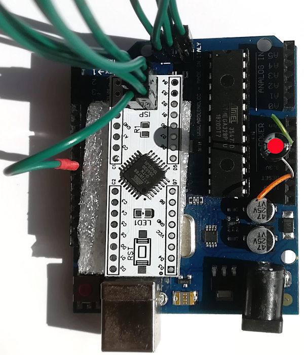
Рис. 5. Программатор Arduino ISP ATtiny Core.
На рисунке 5 противным цветом помечен конденсатор, не забывайте про него. Ножки конденсатора вставлены в разъем Arduino вместе с оголёнными проводами для обеспечения более надёжного контакта.
В терминале (кому командная строка) запустите программу avrdude:
avrdude -pt88 -cstk500v1 -P/dev/ttyACM0 -b19200
avrdude: warning at /home/dior/.avrduderc:56: part 8052 overwrites previous definition /home/dior/.avrduderc:5.

avrdude: AVR device initialized and ready to accept instructions

Reading | ################################################## | 100% 0.03s

avrdude: Device signature = 0x1e9311 (probably t88)

avrdude: safemode: Fuses OK (E:FF, H:DE, L:EF)

avrdude done.  Thank you.
Скр. 3. Программа avrdude считала сигнатуру микроконтроллера и значения фьюзов.
Запуская программу avrdude (см. скриншот 3), уточните значение параметра -P. Это порт к которому подключилась Ваша Arduino. Порт можно посмотреть в программе Arduino IDE (меню Инструменты / Порт).
На скриншоте 3 мы видим значения фьюзов микроконтроллера ATtiny88. В он-лайн калькуляторе можно посмотреть каким настройкам соответствуют эти значения:
Скр. 4. Фьюзы (E:FF, H:DE, L:EF) в он-лайн калькуляторе.
Скриншот 4 подтверждает нашу догадку о том, что заводские установки фьюзов в микроконтроллере ATtiny88 настроены на слишком низкую частоту работы тактового генератора микроконтроллера. А ещё, фьюзы (E:FF, H:DE, L:EF) вроде как и не заводские, а может в калькуляторе не верные сведения под кнопкой "Defaults".
Подберём новые фьюзы:
Скр. 5. Фьюзы (E:FF, H:DE, L:EE) в он-лайн калькуляторе.
Запишем выбранные фьюзы в микроконтроллер.
avrdude -pt88 -cstk500v1 -P/dev/ttyACM0 -b19200 -U efuse:w:0xff:m -U hfuse:w:0xde:m -U lfuse:w:0xee:m
avrdude: warning at /home/dior/.avrduderc:56: part 8052 overwrites previous definition /home/dior/.avrduderc:5.

avrdude: AVR device initialized and ready to accept instructions

Reading | ################################################## | 100% 0.03s

avrdude: Device signature = 0x1e9311 (probably t88)
avrdude: reading input file "0xff"
avrdude: writing efuse (1 bytes):

Writing | ################################################## | 100% 0.01s

avrdude: 1 bytes of efuse written
avrdude: verifying efuse memory against 0xff:
avrdude: load data efuse data from input file 0xff:
avrdude: input file 0xff contains 1 bytes
avrdude: reading on-chip efuse data:

Reading | ################################################## | 100% 0.01s

avrdude: verifying ...
avrdude: 1 bytes of efuse verified
avrdude: reading input file "0xde"
avrdude: writing hfuse (1 bytes):

Writing | ################################################## | 100% 0.01s

avrdude: 1 bytes of hfuse written
avrdude: verifying hfuse memory against 0xde:
avrdude: load data hfuse data from input file 0xde:
avrdude: input file 0xde contains 1 bytes
avrdude: reading on-chip hfuse data:

Reading | ################################################## | 100% 0.01s

avrdude: verifying ...
avrdude: 1 bytes of hfuse verified
avrdude: reading input file "0xee"
avrdude: writing lfuse (1 bytes):

Writing | ################################################## | 100% 0.02s

avrdude: 1 bytes of lfuse written
avrdude: verifying lfuse memory against 0xee:
avrdude: load data lfuse data from input file 0xee:
avrdude: input file 0xee contains 1 bytes
avrdude: reading on-chip lfuse data:

Reading | ################################################## | 100% 0.01s

avrdude: verifying ...
avrdude: 1 bytes of lfuse verified

avrdude: safemode: Fuses OK (E:FF, H:DE, L:EE)

avrdude done.  Thank you.
Скр. 5. Запись фьюзов (E:FF, H:DE, L:EE) в микроконтроллер с помощью программы avrdude и программатора ArduinoISP.
Проверим теперь работоспособность микроконтроллера Tiny88:
avrdude -pt88 -cstk500v1 -P/dev/ttyACM0 -b19200
avrdude: warning at /home/dior/.avrduderc:56: part 8052 overwrites previous definition /home/dior/.avrduderc:5.

avrdude: AVR device initialized and ready to accept instructions

Reading | ################################################## | 100% 0.03s

avrdude: Device signature = 0x1e9311 (probably t88)

avrdude: safemode: Fuses OK (E:FF, H:DE, L:EE)

avrdude done.  Thank you.
Скр. 6. Чтение сингатуры и фьюзов из микроконтроллера с помощью программы avrdude и программатора ArduinoISP.
Ещё раз проверим работоспособность микроконтроллера Tiny88 уже с программатором USBASP:
avrdude -cUSBASP -pt88
avrdude: warning at /home/dior/.avrduderc:56: part 8052 overwrites previous definition /home/dior/.avrduderc:5.

avrdude: warning: cannot set sck period. please check for usbasp firmware update.
avrdude: AVR device initialized and ready to accept instructions

Reading | ################################################## | 100% 0.00s

avrdude: Device signature = 0x1e9311 (probably t88)

avrdude: safemode: Fuses OK (E:FF, H:DE, L:EE)

avrdude done.  Thank you.
Скр. 6. Чтение сингатуры и фьюзов из микроконтроллера с помощью программы avrdude и программатора USBASP.
Подключим через резистор 220 Ом светодиод к микроконтроллеру на порт PB5, ножка микроконтроллера 17, в терминах Arduino это pin13. Резистор подключаем к микроконтроллеру, вторая ножка резистора к аноду светодиода, катод светодиода к GND.
Загрузим в микроконтроллер ATtiny88 из Arduino IDE следующую программу с помощью программатора USBASP:
void setup() {
  pinMode(13, OUTPUT);
}

void loop() {
  digitalWrite(13, HIGH);
  delay(100);
  digitalWrite(13, LOW);
  delay(900);
}
Лист. 2. Программа Blink.
- Запустите загрузку программы Blink в микроконтроллер ATtiny88. Для этого:
- В меню Инструменты / Плата выберите плату ATtiny48/88 (No bootloader).
- В меню Инструменты / Chip выберите ATtiny88.
- В меню Инструменты / Clock Sourse выберите 8 MHz (internal).
- В меню Инструменты / Программатор выберите USBasp (ATtinyCore).
- В меню Скетч запустите Загрузку через программатор.
Как настроить Arduino IDE на работу с микроконтроллерами ATtiny Смотрите в статье ATtiny88 программируем в Arduino IDE.
Посмотрите работу реальную работу Arduino IDE во время загрузки программы Blink в микроконтроллер с помощью программатора USBASP. То что Вы видите на следующем скриншоте обычно спрятано от нас за графическим интерфейсом Arduino IDE.
/root/.arduino15/packages/arduino/tools/avrdude/6.3.0-arduino18/bin/avrdude -C/root/.arduino15/packages/ATTinyCore/hardware/avr/1.5.2/avrdude.conf -v -pattiny88 -cusbasp -Uflash:w:/tmp/arduino_build_160253/Blink.ino.hex:i

avrdude: Version 6.3-20201216
         Copyright (c) 2000-2005 Brian Dean, http://www.bdmicro.com/
         Copyright (c) 2007-2014 Joerg Wunsch

         System wide configuration file is "/root/.arduino15/packages/ATTinyCore/hardware/avr/1.5.2/avrdude.conf"
         User configuration file is "/home/dior/.avrduderc"
avrdude: warning at /home/dior/.avrduderc:56: part 8052 overwrites previous definition /home/dior/.avrduderc:5.

         Using Port                    : usb
         Using Programmer              : usbasp
         Setting bit clk period        : 5.0
         AVR Part                      : ATtiny88
         Chip Erase delay              : 15000 us
         PAGEL                         : PD7
         BS2                           : PC2
         RESET disposition             : dedicated
         RETRY pulse                   : SCK
         serial program mode           : yes
         parallel program mode         : yes
         Timeout                       : 200
         StabDelay                     : 100
         CmdexeDelay                   : 25
         SyncLoops                     : 32
         ByteDelay                     : 0
         PollIndex                     : 3
         PollValue                     : 0x53
         Memory Detail                 :

                                  Block Poll               Page                       Polled
           Memory Type Mode Delay Size  Indx Paged  Size   Size #Pages MinW  MaxW   ReadBack
           ----------- ---- ----- ----- ---- ------ ------ ---- ------ ----- ----- ---------
           eeprom        65    20     4    0 no         64    4      0  3600  3600 0xff 0xff
           flash         65     6    64    0 yes      8192   64    128  4500  4500 0xff 0xff
           lfuse          0     0     0    0 no          1    0      0  4500  4500 0x00 0x00
           hfuse          0     0     0    0 no          1    0      0  4500  4500 0x00 0x00
           efuse          0     0     0    0 no          1    0      0  4500  4500 0x00 0x00
           lock           0     0     0    0 no          1    0      0  4500  4500 0x00 0x00
           calibration    0     0     0    0 no          1    0      0     0     0 0x00 0x00
           signature      0     0     0    0 no          3    0      0     0     0 0x00 0x00

         Programmer Type : usbasp
         Description     : USBasp, http://www.fischl.de/usbasp/

avrdude: set SCK frequency to 187500 Hz
avrdude: warning: cannot set sck period. please check for usbasp firmware update.
avrdude: AVR device initialized and ready to accept instructions

Reading | ################################################## | 100% 0.00s

avrdude: Device signature = 0x1e9311 (probably t88)
avrdude: NOTE: "flash" memory has been specified, an erase cycle will be performed
         To disable this feature, specify the -D option.
avrdude: erasing chip
avrdude: set SCK frequency to 187500 Hz
avrdude: warning: cannot set sck period. please check for usbasp firmware update.
avrdude: reading input file "/tmp/arduino_build_160253/Blink.ino.hex"
avrdude: writing flash (476 bytes):

Writing | ################################################## | 100% 0.24s

avrdude: 476 bytes of flash written
avrdude: verifying flash memory against /tmp/arduino_build_160253/Blink.ino.hex:
avrdude: load data flash data from input file /tmp/arduino_build_160253/Blink.ino.hex:
avrdude: input file /tmp/arduino_build_160253/Blink.ino.hex contains 476 bytes
avrdude: reading on-chip flash data:

Reading | ################################################## | 100% 0.17s

avrdude: verifying ...
avrdude: 476 bytes of flash verified

avrdude done.  Thank you.
Скр. 7. Так Arduino IDE загружает в микроконтроллер программы.
Для наших экспериментов с микроконтроллером ATtiny88 Ефимом Сысоевым была разработана принципиальная электрическая схема и печатная плата. За это большое спасибо Ефиму. Плату можете купить у нас.
Рис. 6. Принципиальная электрическая схема переходника TQFP32 to DIP с периферией для экспериментов с микроконтроллерами ATtiny88 и аналогичными.
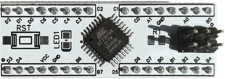
Рис. 7. Плата с микроконтроллером ATtiny88 в корпусе TQFP32.